
It’s been decades since I’ve taken care of a dog, so when my family got Fuji in 2025 I had to come up with ways to remember all of the important things we need to do to take care of her. Usually people say to get into a routine and just follow it, but I know that sometimes I need reminders to keep track of what needs to get done and when. One of the big ones, of course, is coming up with a consistent feeding schedule.
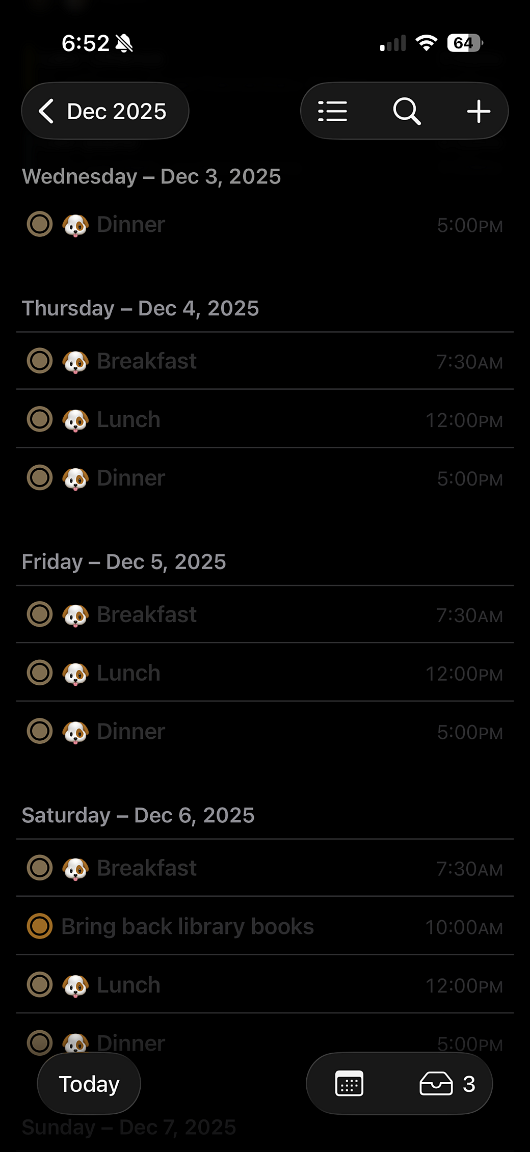
Since she was only a few months old, we established a routine around three meals a day. I added each meal to a list in iOS Reminders and set each reminder to repeat every day. This works really well in that I can see what meals I've already fed to her and after the time for a meal occurs I can see a constant reminder to feed her whenever I look down at my phone.
In iOS 18, Apple made it so you can see your reminders on the Calendar app, and I loved this idea. Combining the calendar and reminders list was one of the main reasons I kept using Fantastical for years, however, unlike Fantastical, you couldn’t decide which Reminders lists you want to appear in the Apple Calendar app. So that means every day I have at least these three items and sometimes that makes it hard to look ahead and make plans because these reminders would push off evening events into a hidden list, revealed by a more button.
It’s only an inconvenience, but still worth it as the actual reminders have been helpful so far. But I got to thinking about ways to remove these items from my calendar while still keeping track of what meals Fuji has had for the day. I was inspired by an LED project done by a friend, and Casey Liss’ Status Board project, to get back into electronics and see what I can do with today’s LED tools and software. But first, I had to do some homework.
Electronics in a New Light
Some day I’ll finish up the drafts and publish the blog posts around some of my earlier DIY LED projects, but to summarize, for a few years I had a stretch of making things using Arduino boards that controlled BlinkM and Adafruit’s NeoPixels LEDs. While I had no formal electronics training, I found enough resources at the time to figure out how to wire up addressable LEDs and to work with Processing and Arduino software to animate the LEDs.
At one point I created an Adobe Flash-based tool to animate a grid of LEDs when plugged into a laptop. I also created an HTML-based tool that generates code that can be copied into Processing and flashed onto the Arduino so you can toggle through a set of animations with a hardware button. Both tools were written just for me and are now lost in time, but the electronics concepts and some of the basics around working with microcontrollers and addressable LEDs stuck with me.
My friend, Ian, introduced me to WLED and showed me a project he had created using LED strips inside wood that was carved out with his CNC and diffused with acrylic pieces he had cut with his laser cutter. He showed me how WLED can be triggered by pushbuttons and how easy it was to use WiFi to jump into the microcontroller and make changes to its settings. Ever since then, I’ve been looking for an excuse to make something with WLED to try it out.
WLED Hello, World!
To get started, I just wanted to do a mini version of Ian’s project. I wanted to get an RGBW LED strip to light up and animate, then use a button to toggle through a set of animations. As is customary in modern times, I went to YouTube to learn how to do that.
While I found a few videos that went over the basics of how to work with WLED and had suggestions on how to power LED strips, I found this video covered exactly what I wanted to accomplish.
I told Ian about my project, and he graciously lent me one of his ESP32 microcontrollers so I could try it out before investing too much into this project. I tried using the old NeoPixel strips I had in the basement and some old buttons I had laying around, but ultimately, after a few frustrating attempts, I wound up buying almost all new stuff as per recommended from some of the videos I was watching.
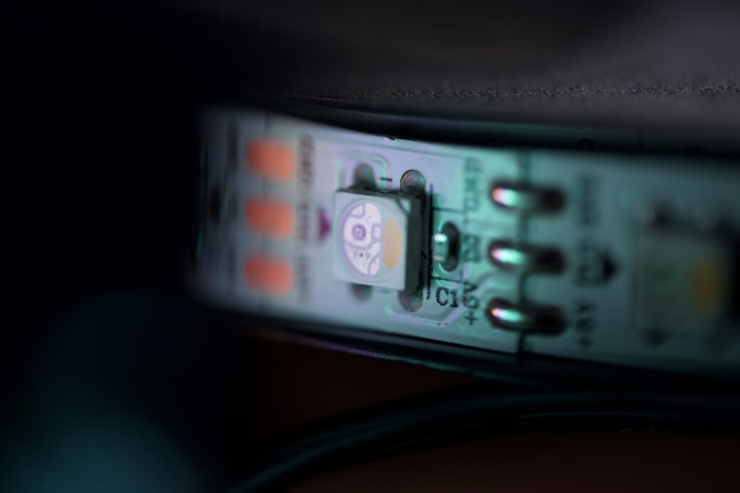
I got a strip of 300 SK6812 RGBW lights because they only used 3 lines: 5V, ground, and a data line. Also, while this project doesn’t really need the white light settings, I got them in Neutral White so in a future project I can take advantage of having a dedicated white diode.
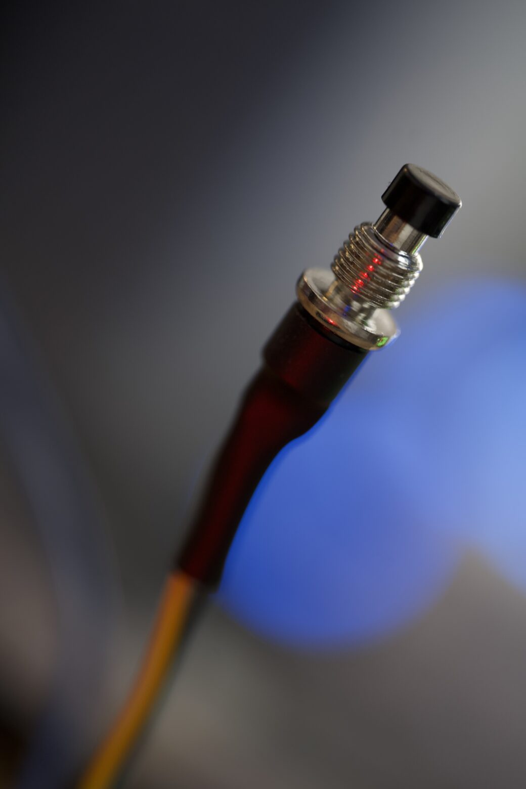
I got the same two-wire pushbuttons as recommended in the video. These are simple, small, and come with spring washers and nuts so it’s very likely I’ll have a use for the other 29 that came in this pack.
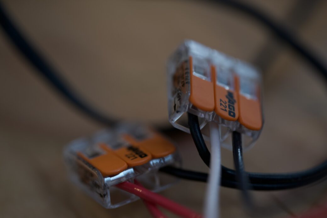
I got a big pack of Wago clips in sizes two, three, and five. I understand that for most LED projects you want to solder where you can, but for this light I wanted to be able to go back in and adjust things without twisting wires or desoldering, and these clips make it easy to do that.
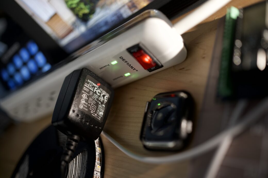
I had a 5V 2A power supply already, so I used it for this project. I wasn’t sure exactly how much power I would eventually need, but I figured 2A would be enough to get started and I could purchase a bigger power supply if I wound up needing it.
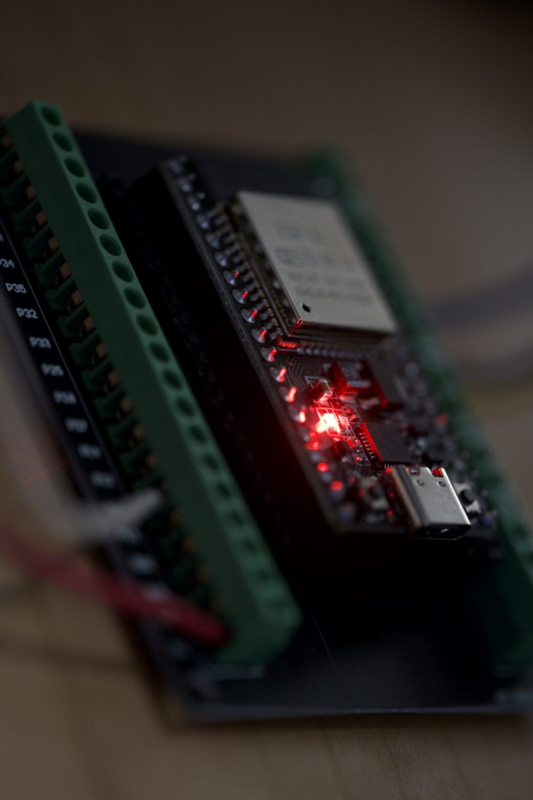
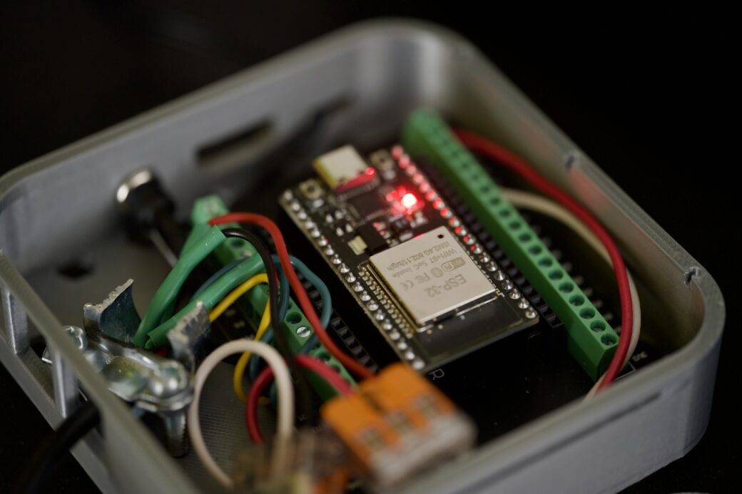
I wound up ordering my own three-pack of ESP32 boards with dev shields. The shields are the part you put the microcontroller into and they make it easy to drop breadboard wires into the top or screw them into the sides for the labeled pins. I got three boards because I wanted to get one for the actual pet light project and a second board that I can keep around for future testing.
To be specific, I got a NodeMCU ESP-32S USB-C. I found out through this project that when people say ESP32, it’s like saying a Raspberry Pi board. The ESP32 is just the main processor and each board variation has their own specs, which sometimes means different hardware and different pin numbering. I found this handy website with detailed specs on the exact board I was working from.
3D Printing FTW
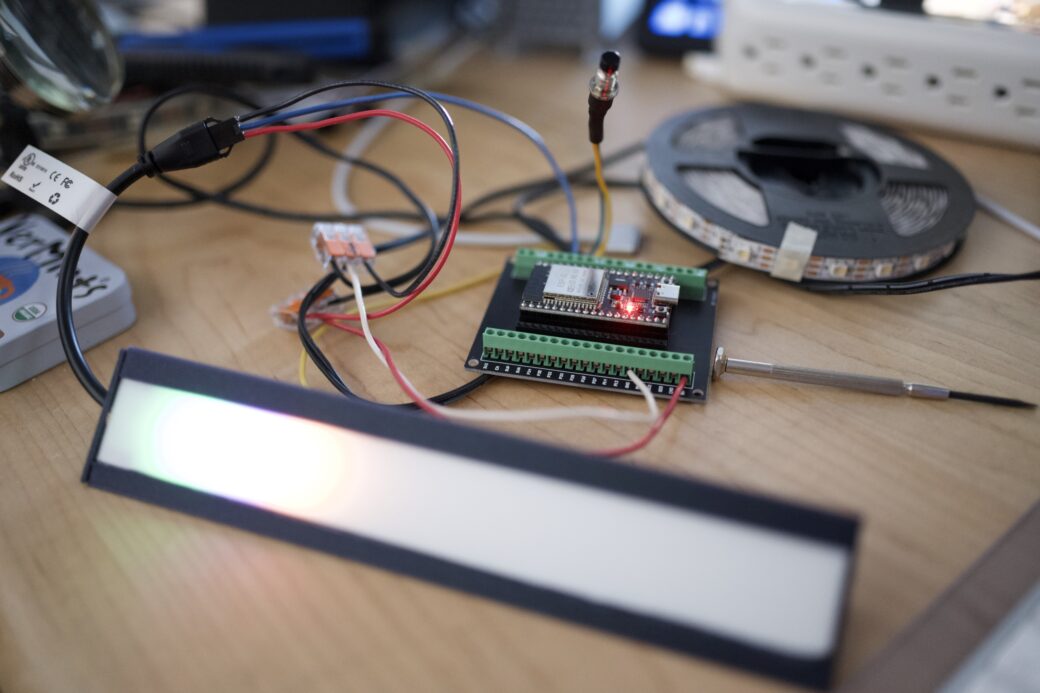
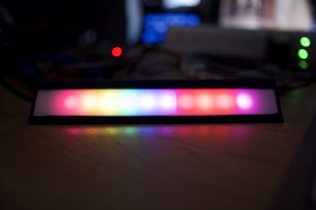
Okay, so the first thing I did was got WLED flashed onto the ESP32. While it’s not my personal browser of choice, I had to use Chrome to install the WLED software because Chrome let me connect the browser to the ESP32 board over USB-C. From there I sort of followed along with the video to set up my network settings and to configure my LED strip. I had cut the strip down to the first 10 LEDs, wired the strip and one pushbutton to my ESP32 board, and then hooked them all up to the power supply. It was incredibly straightforward and I was psyched to see the LEDs changing colors as I played around with WLED’s built-in effects.
While I was learning my way through the circuitry side of things, I was also printing a small enclosure for the LED strip. I wanted to see how my white PLA filament would look as a diffuser, so I found this model on Printables and printed the parts that I needed.
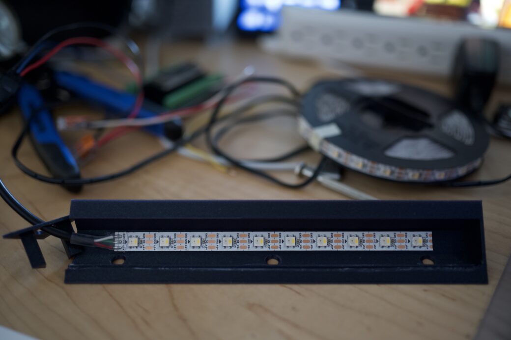
The model is a Toblerone-like shape with a flat part to mount an LED strip and a set of grooves where you can slide in a flat piece of filament across the front.
At this point I had gotten sort of an MVP of all the potential pieces worked out (the diffusion being that last thing to think about). Just for fun, and so I could eventually take this whole rig to another room in the house, I also printed another model that I found on Printables to act as an enclosure for the ESP32 and the wiring.
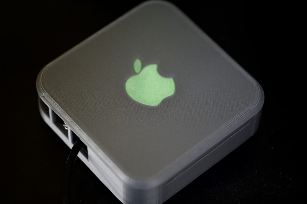
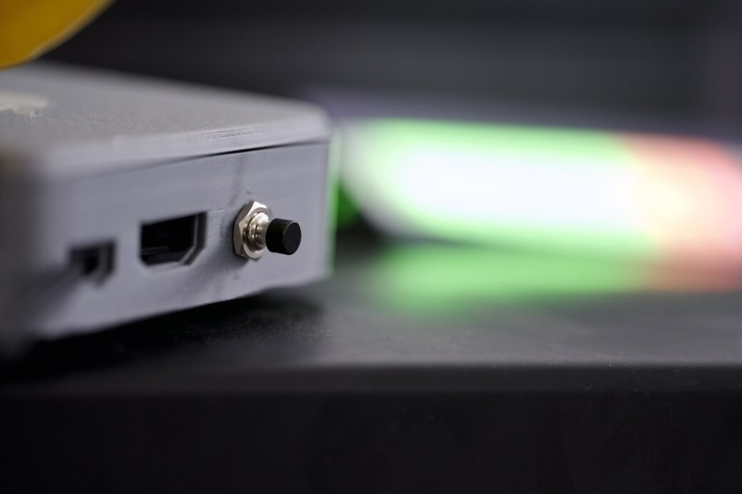
The Mac mini box was originally for a Raspberry Pi, so I modified it a little bit in Bambu Slicer to remove the pegs that mount your Pi onto the bottom part. I also used a hole in the back to mount my pushbutton.
Software Design
Okay, so back to the pet feeding light. While all of this ordering and 3D printing was going on I was thinking through the actual software and how this light would work.
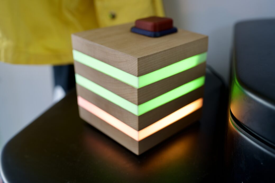
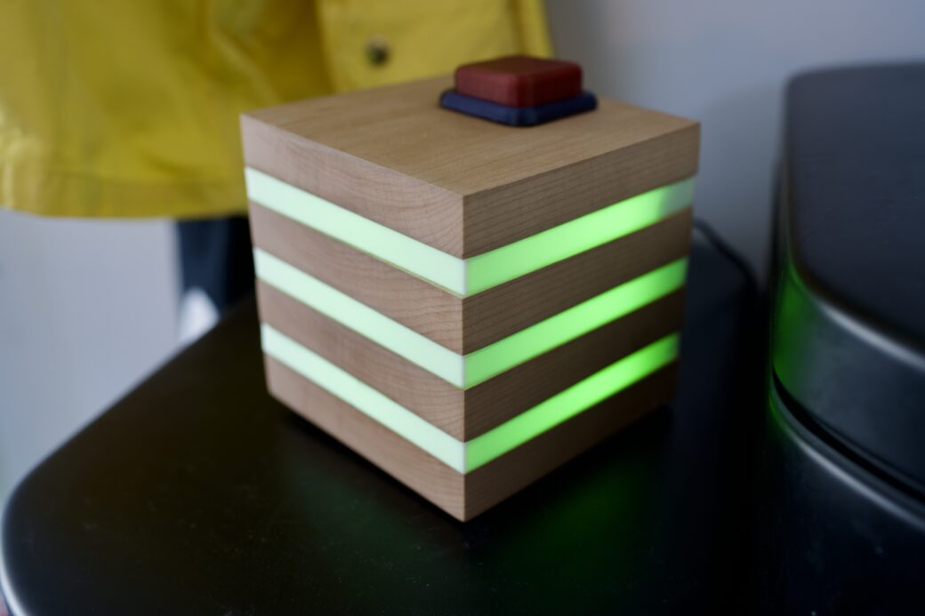
The requirements are that every day I want to press a button after putting down each meal and to see one of three LEDs light up to indicate which meal was already fed. Every night, the software should reset the lights so in the morning I would start back from zero.
The software engineer in me thought about using my personal server Mac mini to run Home Assistant and an Express server so I can use my home network to talk between a button I push and some sort of LED strip. I wanted to use the Express server so I can write the daily feeding button pushes to JSON files that essentially saved the state and kept feeding records (for some reason). I was working it all out and looking into what MQTT does, but over the course of a couple of weeks I realized that A. I don’t need to record any of this, and B. if I can find a way to keep the state of the button push (breakfast, lunch, or dinner) on the ESP32, I could contain everything into one place.
While I had been learning about WLED segments and presets, I learned that you can create a preset that just cycles through a list of other presets that you’ve defined:
P1=1&P2=3&PL=~This was an example I found in another YouTube video, but if you wanted to do more with the built-in API, they have a reference sheet for all of the supported commands.
Running this command turned out to be all I needed. I would create three presets and made sure they had IDs 1, 2, and 3. Then I created the preset to run this command and hooked it up to the button push.
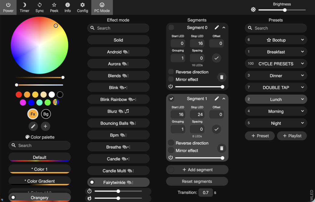
Segments allow you to have some LEDs using one effect while the other LEDs in the strip use a different effect.
For fun, I added a rainbow effect when you long-press the button and a crazy flashing disco mode when you double-tapped the button. WLED also has a scheduling mode, so I created two more presets and have them triggered late at night and in the early morning. This essentially took care of the reset requirement.
Hardware Design
Okay, so I knew how the software would work, and now I needed to figure out what this thing would look like. In my head, it was just a little set of three LEDS and a button inside of a 3D-printed enclosure with maybe a wooden facade on the front. I thought about putting this over where our dog food storage containers live so maybe I would hang it on the wall or let it sit on one of our food storage containers. There is an outlet behind the food storage containers so it was a good spot for it.
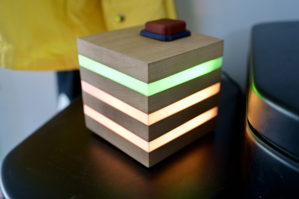
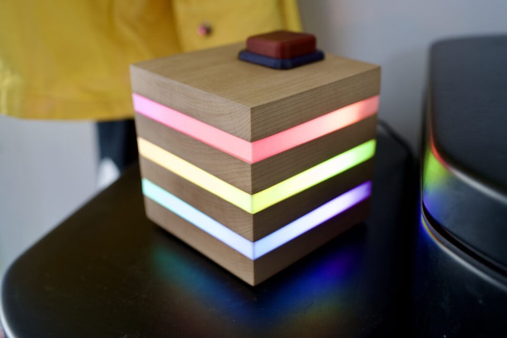
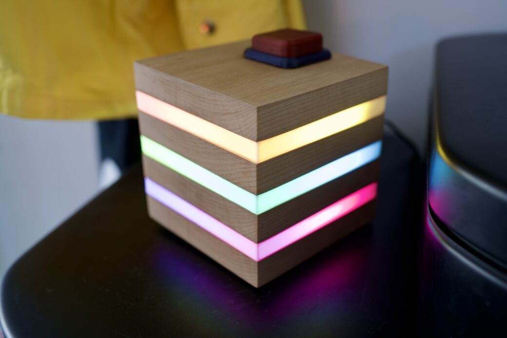
At this point I was looking for inspiration and Googled wood and LED strips. I found a cube-shaped lamp that had pieces of wood separated by strips of acrylic with LEDs inside. While I explored a few other ideas, I came back to this one and decided to sketch up how I thought it might work.
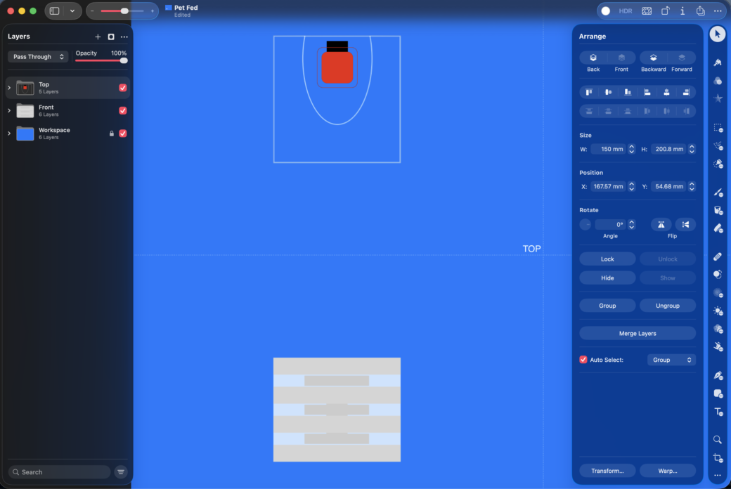
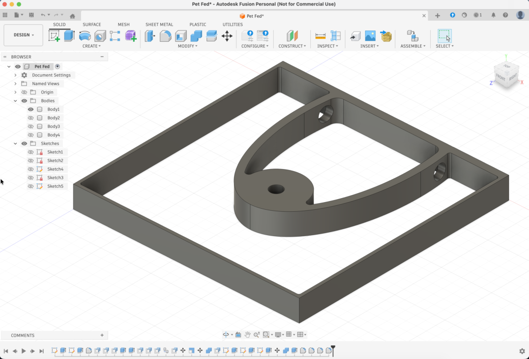
I used the newly-released Creator Studio version of Pixelmator Pro to work out what I thought should be the proportions of wood to plastic and then I created a top down view that I would eventually pull into Fusion to model out the 3D printed button and the diffusion layers.
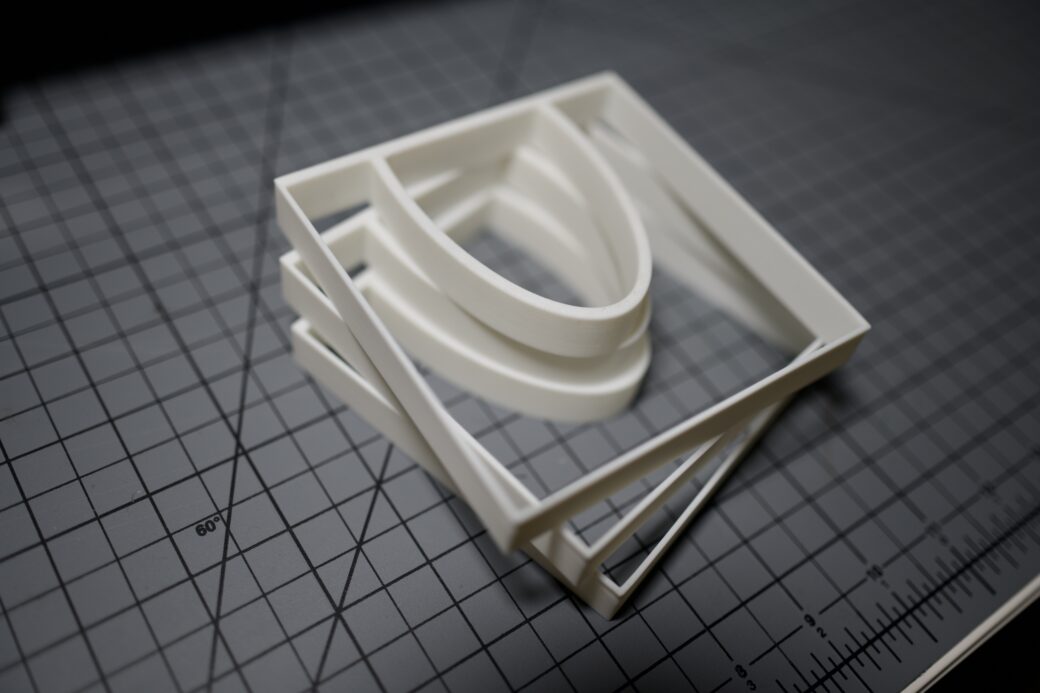
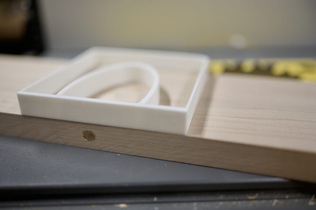
I made a few prints of the diffusion layer to get an idea of what size I wanted the lamp to be.
The design included this half oval shape that I planned on mounting the LED strips to the outer portion. Then on the inside I planned on leaving a cavity so all of the wires, the button, and the microcontroller could fit with a little extra room to spare.
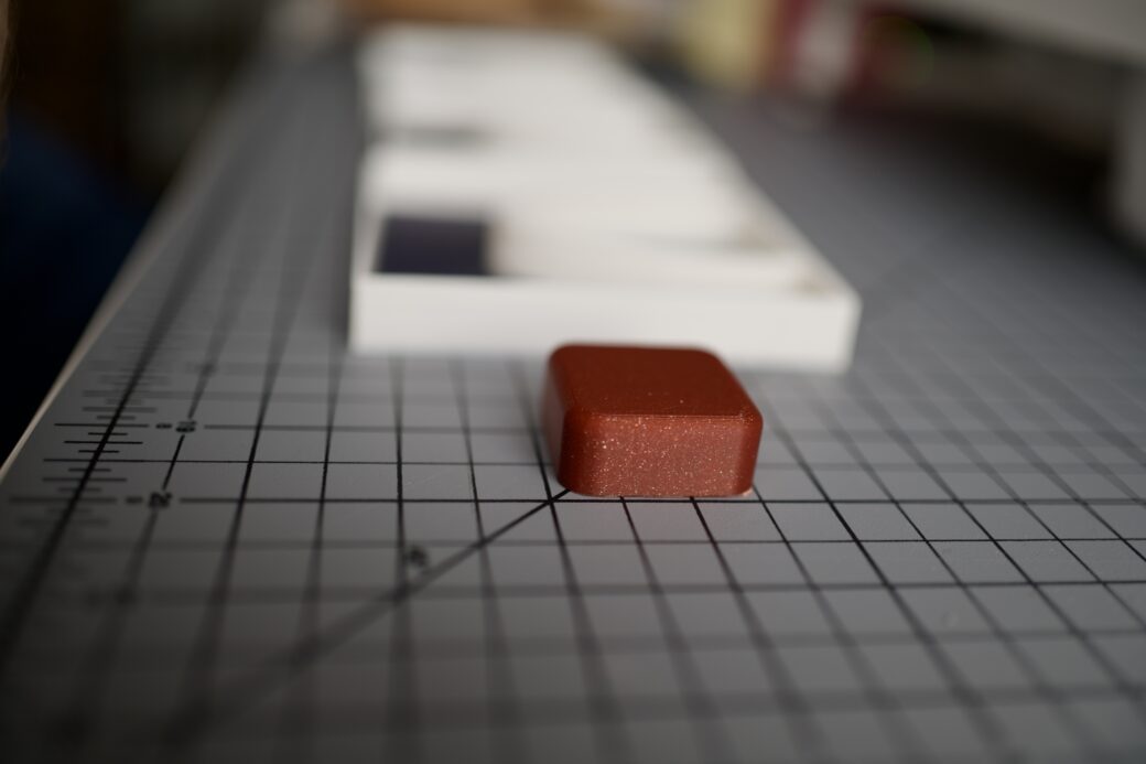
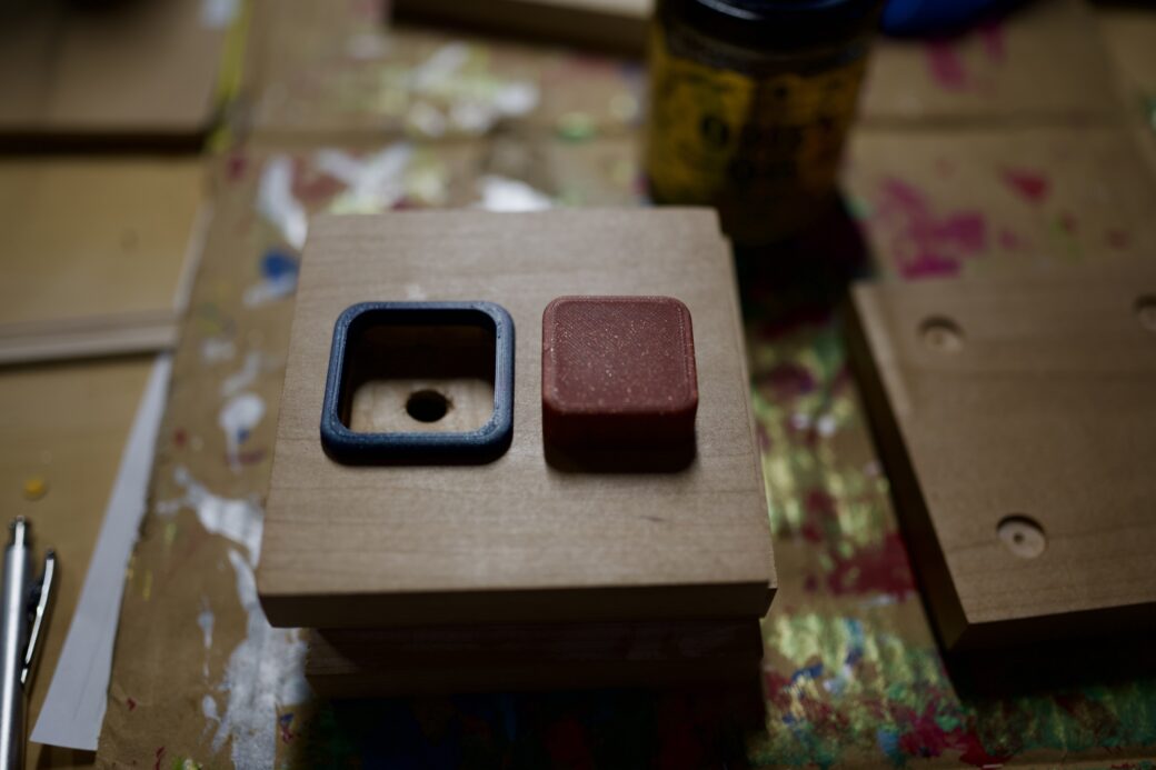
The button was as simple as you can get, with a few rounded corners and a flat bottom.
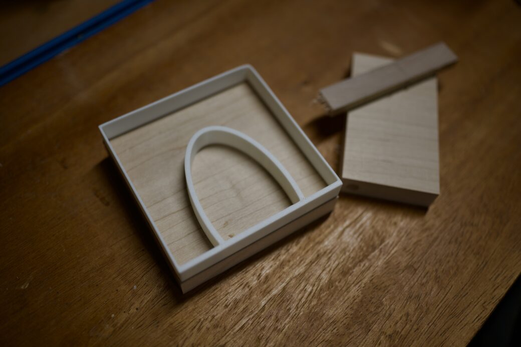
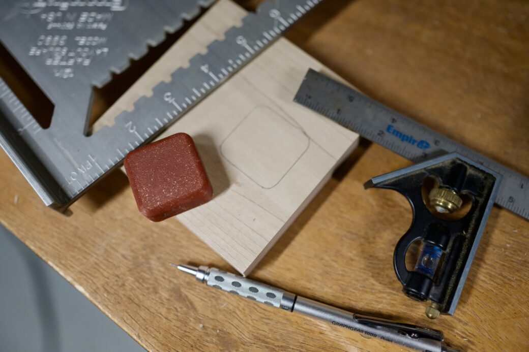
I took the diffusion layers down to my workshop and dug up a piece of scrap maple that I had been looking for a good project to use it on. The maple was part of a shelf I was putting together, so it had these dowels in it, but the size of this light would work out perfect if I could cut around the dowels.
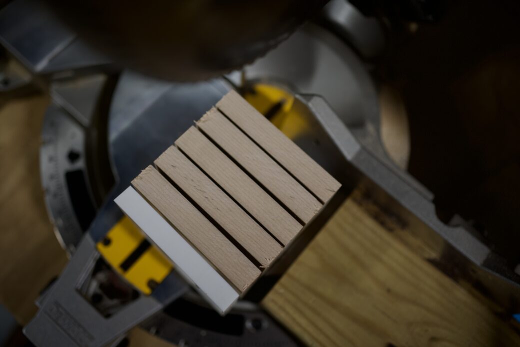
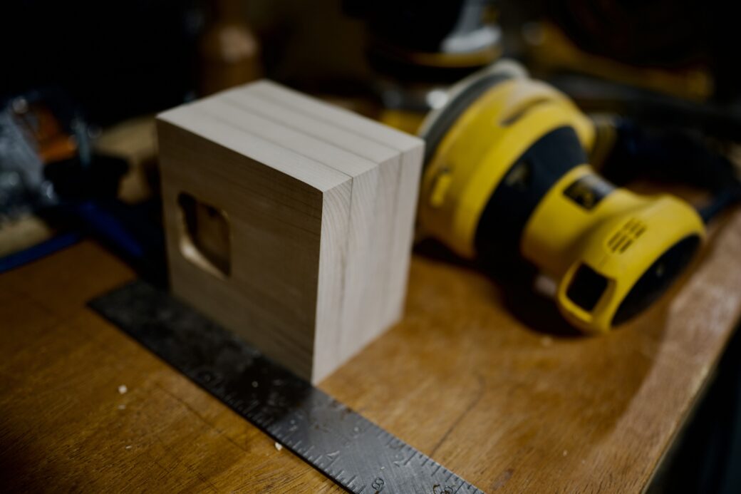
I ripped a long enough strip of maple on the table saw, then used a miter saw to cut the right size for the light, while chopping off the dowel parts as I went. I cut an extra piece so I had a spare, in case my next few steps went awry.
I stacked up all of the layers and while I thought the proportions didn't look right, at least the size of the wood felt good.
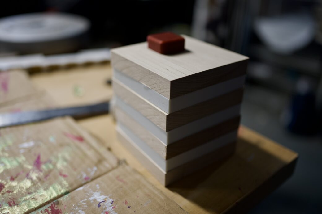
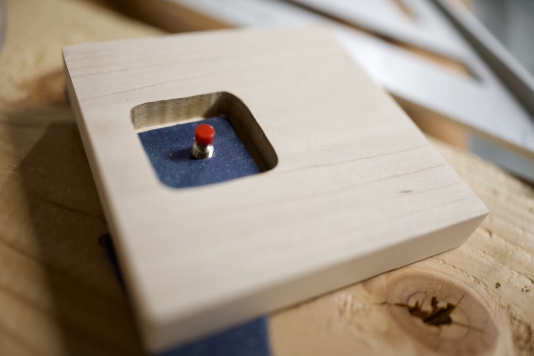
I traced the button and spent some time with my router to dig out the area for the button to sit. I dug about two-thirds into the top piece.
I rigged together a guide to hold the pieces into place while I gave them a rough sanding.
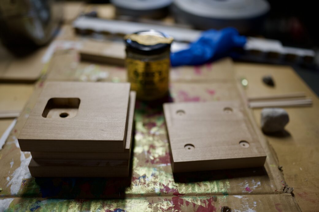
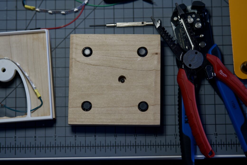
Then I brought the bottom piece over to the drill press and added spots for some rubber feet.
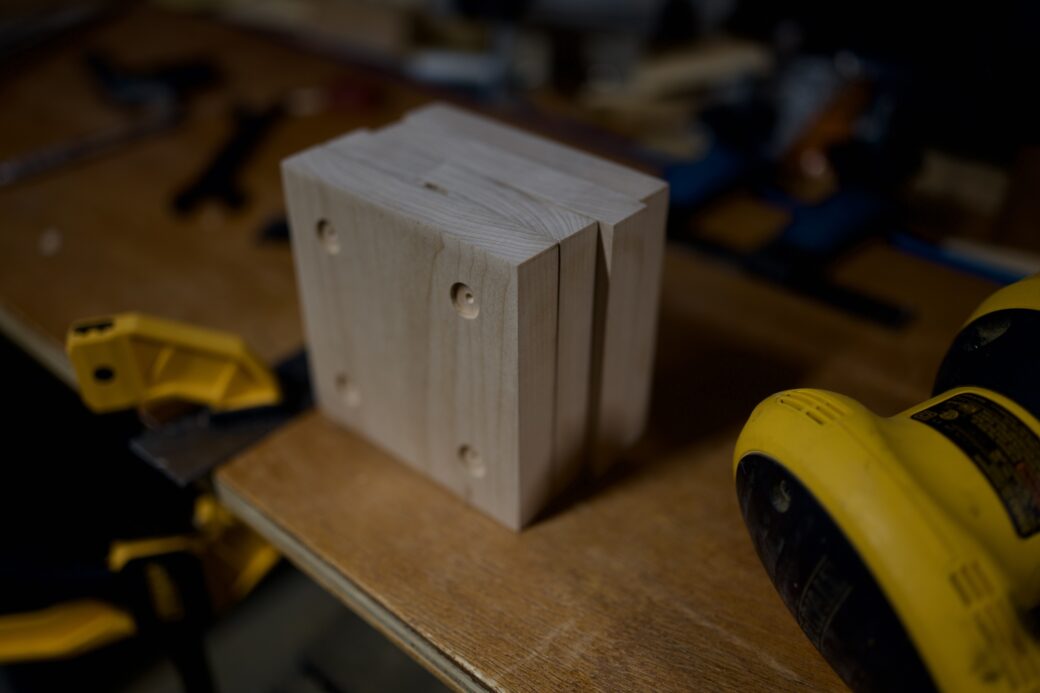
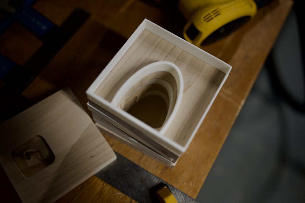
While over at the drill press, I swapped in a Forstner bit to cut the cavity into the two center pieces. Because it didn’t affect the LED output and you couldn’t see it from the outside, I created three quick holes and used the router to smooth out the remaining bits enough to get it close to the half-oval on the diffusion layers.
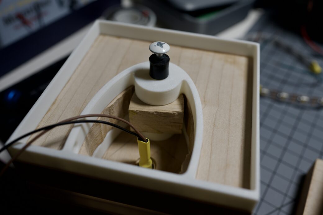
I drilled a hole into the top layer and mounted the button to a scrap piece of plastic and then placed that into the hole. eventually this plastic would get glued into place, but for now I was dry fitting everything.
With all of the wood cuts made, I applied some of my favorite Odie’s Oil finish to the outside. I let that dry over night while I started to wrap up the 3D printing parts.
Wood × 3D Prints
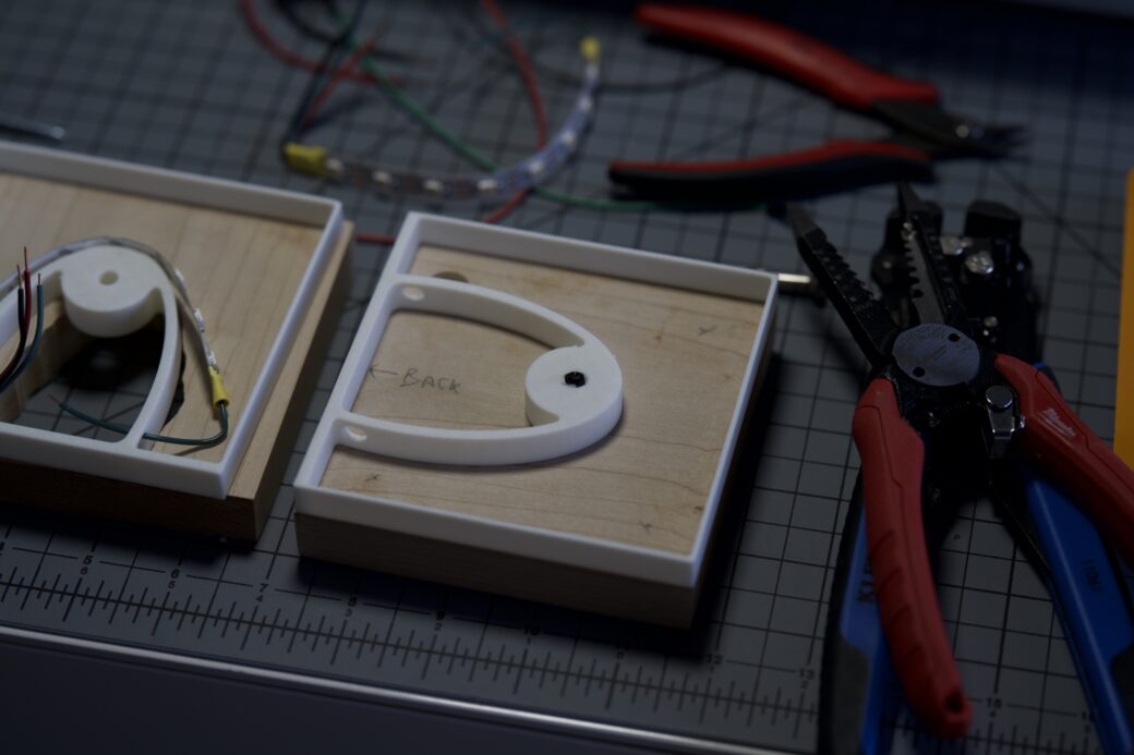
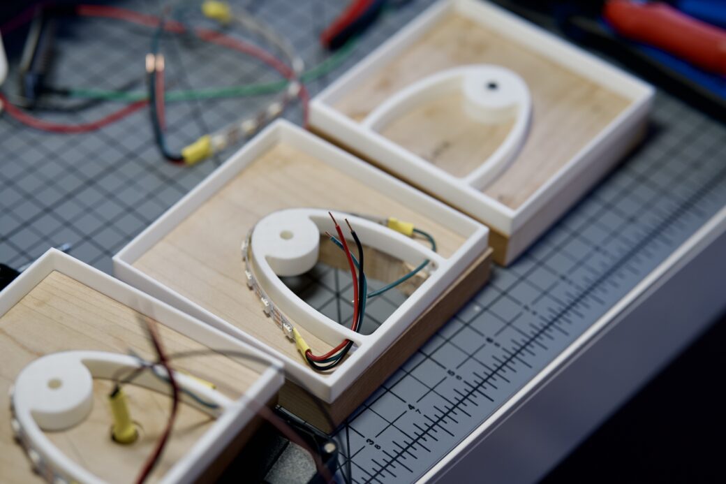
I got to thinking about how I would run the wires to the different layers and I realized I needed to have some sort of opening on both sides so I can run power into one side and then data out of one and into the next layer.
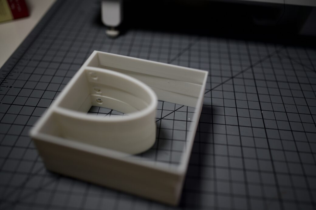
My first attempt to address this was to drill holes into the sides of the half-ovals. This would work, but I decided to reprint the diffusion layers one more time anyway. The reprint included these holes, made the height of each layer a little shorter, and added support and a hole near the center of the light where I could use screws to keep the whole light together when it was assembled.
While those were printing I designed a quick ring to put around the button. This was mostly to hide the cutout of the wood, but also, while the focus of the light was around the LED and wood layers, I wanted the button to look over the top and almost cartoonish.
After one last dry fitting I glued on the feet, the button components, and I used epoxy to glue one layer of wood to each layer of filament.
After the glue dried, I put in a long screw that went from the top piece of wood down into the diffusion layer of the second piece. I had to get creative with a couple of spacers to make the length of the screw line up without going through the top.
Later on I would also add a couple extra screws to attach the 3rd row to the 2nd row.
On the bottom piece, I just wanted to use a small screw so I could easily access the wiring without taking the whole thing apart. I was thinking of using epoxy to glue a nut onto the bottom diffusion layer, but because epoxy can be messy and it’s very permanent, I took my soldering iron and pressed the nut down in to the 3D filament. This created a perfect fit to hold the nut into place but allowed me to take it out if I needed to.
I lined up this nut and made an indented hole in the bottom piece for the screw.
From here I just needed to wire everything up. I worked on the different layers, from top to bottom. I had cut out 8 LEDs for each layer and I soldered the power and data lines to the appropriate sides. I tried to leave just enough wire based on what layer each strip would be on so the data wires could reach the next layer and the power wires could come together into one Wago clip.
I pulled the power supply wire in through a happily accidental hole in the back of one of the layers and screwed everything together one more time. I wired everything up to the ESP32 and carefully stuffed it all into the cavity. Then I plugged it in and it came to life!
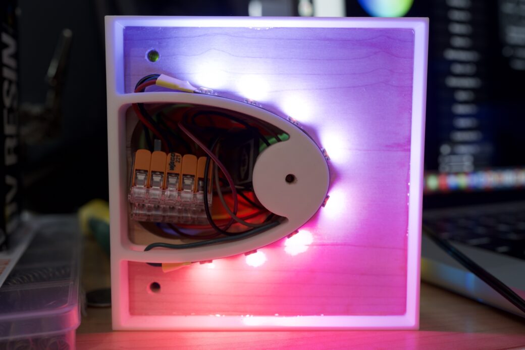
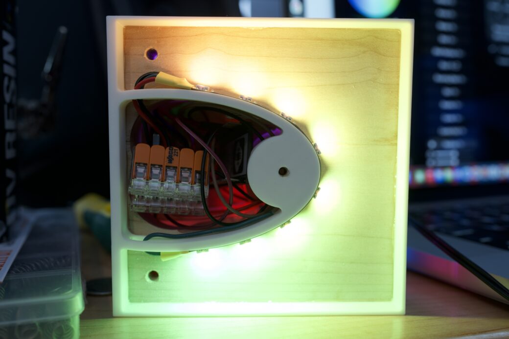
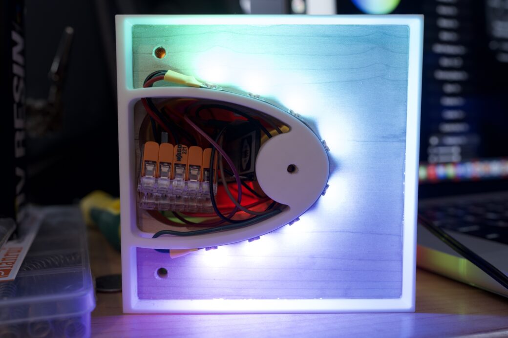
I was really happy with how the 3D-printed diffusion worked out. A lot of that was a guess, like how much distance between the half oval and the walls of each diffusion layer was enough that you can’t see any individual LED, but it’s also close enough that the lights blend together smoothly.
This project isn’t an original on a couple accounts, but it got me back into exploring the exciting things you can do with LEDs and microcontrollers. Compared to when I was doing this 15 years ago, there’s a lot less friction and a bunch more resources to learn from. WLED isn’t the only LED programming game in town, but you can do a whole lot with its basic features. I thought I would spend more time generating my own animations and exploring their APIs, but for this simple project I just didn’t wind up needing to take it any further than what you can do out of the box.
I didn’t mention this above, but one lesson I need to think more about is on the assembly portion of this kind of thing. I wound up winging it towards the end a little bit because I didn’t have a good plan for how to stack things together and make it so I could access each layer again later. That said, I was able to fit all of the electronics inside of it and I didn’t have to make any compromises to the design.
Another thing I need to think about before the next one is where power regulation comes into play. My understanding is that the LED strips tend to have their own resistors built in, but for projects with more lights I’ll want to spend more time looking into power supplies to make sure there's enough power and that when the power is turned off or on there are no negative effects.
Now that I have a 3D printer, I think it’s amazing to be able to draw an SVG and then a few weeks later have a fully functioning lamp. This might be just the beginning of a new LED maker journey. I already have ideas for a couple more places to go next.